Building Your Own Roll-off Roof Observatory (Parts 1 and 2)
This article was originally written in 2002 and has been uploaded due to the many requests I have received concerning this article. Please note that almost 15 years is an eternity in this hobby and many things have changed...even the way I would do things now.
In fact, Ballauer Observatory, as originally built, no longer exists. However, the design principles should transfer to any of today's needs. Just do your own research whereas today's technology can improve your actual design. Your mileage may vary.
The original article was written in two parts, "Designing a Roll-off Roof Observatory" and "Construction of a Roll-off Roof Observatory." I have merged the two articles below under the title you see above.
Part 1
Introduction
There are so many advantages to building an observatory that naming them all would be unnecessary except to say that your observing time will go up exponentially. That was the problem I had before. When you own a 10” Meade SCT, observing can become a major chore. We all know the routine: 30 minutes of setup; 1 hour of temperature acclimation; resetting the azimuth because Mars at 300x isn’t staying in the field of view long enough; galaxies, nebulae, and globulars are too dim because of light pollution; studying the waning moon to salvage something out of the evening; 30 minutes of teardown; and going home to doctor all the mosquito bites.
If nothing else, the Ballauer observatory serves its primary purpose to make me a more active and consistent observer. Setting up now involves simply turning on a couple of switches. Temperature acclimation is immediate. CCDs and computers are ready for action (something that takes extra time and power while in the field). The possibility of more advanced explorations into spectroscopy and astrometry become feasible.
If you are serious about this hobby…build yourself one!
For this reason, I’ve documented the planning and construction of my own roll-off roof observatory. The extent of this article goes beyond a simple scope enclosure and it is written primarily for those with more ambition and a bigger budget; a permanent structure where you plan on staying for many years. But regardless of the type or size of observatory you plan on building, just about everyone should be able to glean something from this article. At the least you should be able to take some of the ideas that you see here to construct your own in much the same way that I have borrowed ideas from others. If you have any questions regarding techniques or designs, feel free to email me at [email protected].
The design phases on this page are generic suggestions and general observations. I’ve supplemented the article with images of my own observatory so as to help illustrated some points. And now, let’s move into the…
Design Phase
The first step to building an observatory is obviously the planning/design stage. I cannot stress enough the importance of doing your homework here. You can save yourself time and money in the long run with a proper plan. Even if you have proficient carpentry skills capable of building a “shed” using the “just wing it” principle, you will eventually find out that the typical shed leaves much to be desired for the function in which you intend to use it. Trust me on this…do your homework.
Pre-Planning
As I began drawing up the design, more and more items kept popping into my head. This is the appropriate time for such ideas to pop up. Even still, things inevitably will keep popping up even during construction! For this reason, staying within budget is very difficult; however, planning well can make the difference between sleeping in your own bed, or in your wife's doghouse. Such ideas for your observatory will arise from having asked yourself the following three questions:
Site and Foundation Issues
Certainly you have chosen your site wisely prior to designing your observatory…right? Just a few comments here. Don’t let the fact that your skies are not as dark as they should be dissuade you from building your structure. Yes, visual observing will take a hit, but CCD imaging can compensate for any light pollution that remains. Any robotic system will succeed in some fashion regardless of the amount of stray photons flying around. Ballauer Observatory was constructed with this thought in mind. My 4.5 - 5.0 magnitude skies do not allow for great visual observing, so I usually pack up and go out to a dark site when that bug strikes me. But the CCD aspects of the hobby tend to make up for it. Though my eyes can't see some objects well in my skies, my SBIG STV becomes my eyes, permitting fully controlled visual observing from the computer monitor or CCD imaging. Plus, the observation of solar system objects do not require dark sky sites anyways. Likewise, the ability of CCD imagers to layer shorter exposures will allow for some pretty, detailed photos.
Next, do not let a lack of low horizons prevent you from building your observatory where you want it to be. Realistically, most of your imaging should be accomplished close to the zenith anyway. In my opinion, and perhaps contrary to that of the populace, the most important horizons should be ranked in order: South, North, and West/East (assuming the lack of the presence of local light pollution and that you live in the Northern hemisphere). So, if you have only one open horizon, make it the Southern exposure. Also, give yourself plenty of Northern sky if possible. Doing this will allow you access to any and all of the celestial objects that are within your reach. For example, many great photographs of Northern objects become possible. Likewise you can cheat a bit on East/West horizons because those objects will be in view eventually anyway, as long as you have provided clear lines to the north and south.
As for orientation, I think you need to roll your roof off in the area of greatest obstruction or light pollution. Most people say to roll the roof off to the North. My question is, “Why?” If you have a dome of light rising 30 degrees over your eastern horizon, as I do, then why obstruct the northern horizon? Using this logic, the argument concerning orientation of the observatory is superfluous. Just make sure that if your roof is tall enough to cause an obstruction, roll it off in the direction of your most obstructed, or most light infested horizon.
Before you start purchasing the materials, please consider some other issues concerning your site and foundation planning...
Construction Plans
Before you begin building, draw some plans! Even if they are merely sketches, the visualization will help greatly and will allow you to catch any mistakes before you actually make them. For example, I planned my observatory as a split roof design, where the roll-off roof has to glide underneath the eave of the permanent roof covering the control room. Without measured drawings of your observatory, you might run into the problem of not providing the necessary clearance for the roll-off roof. I got lucky on mine. My original design called for the roof to roll off on angle iron placed in an 'L' position, where the wheels are protected on both sides by the angle iron. After framing the building, I decided against this roof plan and opted for 'V' grooved wheels on an inverted angle iron track (I got the idea for this from Chris Vedeler's observatory here ). This increased the roll-off roof height a full inch. Not good considering that I originally planned a one-inch clearance at the eaves of both roofs (where both roofs meet at their closest)! When I finally placed the roll-off roof on its tracks, the eaves actually rubbed slightly when I closed the roof. I fixed it by shaving a bit off the upper eave. Close call.
But knowing that I drew the plan precisely on paper gave me a pretty good idea that changing the roof design mid-construction would still work for me. My suggestion to you is to know every nook and cranny of your structure before you build it. The only way to do this is by completing measured drawings of your observatory.
Ballauer Observatory is based on a 10 x 20 ft. floor plan. The control room covered an 8 x 10 area and the observing room a 12 x 10 area as shown:
There are so many advantages to building an observatory that naming them all would be unnecessary except to say that your observing time will go up exponentially. That was the problem I had before. When you own a 10” Meade SCT, observing can become a major chore. We all know the routine: 30 minutes of setup; 1 hour of temperature acclimation; resetting the azimuth because Mars at 300x isn’t staying in the field of view long enough; galaxies, nebulae, and globulars are too dim because of light pollution; studying the waning moon to salvage something out of the evening; 30 minutes of teardown; and going home to doctor all the mosquito bites.
If nothing else, the Ballauer observatory serves its primary purpose to make me a more active and consistent observer. Setting up now involves simply turning on a couple of switches. Temperature acclimation is immediate. CCDs and computers are ready for action (something that takes extra time and power while in the field). The possibility of more advanced explorations into spectroscopy and astrometry become feasible.
If you are serious about this hobby…build yourself one!
For this reason, I’ve documented the planning and construction of my own roll-off roof observatory. The extent of this article goes beyond a simple scope enclosure and it is written primarily for those with more ambition and a bigger budget; a permanent structure where you plan on staying for many years. But regardless of the type or size of observatory you plan on building, just about everyone should be able to glean something from this article. At the least you should be able to take some of the ideas that you see here to construct your own in much the same way that I have borrowed ideas from others. If you have any questions regarding techniques or designs, feel free to email me at [email protected].
The design phases on this page are generic suggestions and general observations. I’ve supplemented the article with images of my own observatory so as to help illustrated some points. And now, let’s move into the…
Design Phase
The first step to building an observatory is obviously the planning/design stage. I cannot stress enough the importance of doing your homework here. You can save yourself time and money in the long run with a proper plan. Even if you have proficient carpentry skills capable of building a “shed” using the “just wing it” principle, you will eventually find out that the typical shed leaves much to be desired for the function in which you intend to use it. Trust me on this…do your homework.
Pre-Planning
As I began drawing up the design, more and more items kept popping into my head. This is the appropriate time for such ideas to pop up. Even still, things inevitably will keep popping up even during construction! For this reason, staying within budget is very difficult; however, planning well can make the difference between sleeping in your own bed, or in your wife's doghouse. Such ideas for your observatory will arise from having asked yourself the following three questions:
- How much am I going to spend on this thing?
Let me provide you with a little bit of perspective. You will discover eventually that the most important accessory to your hobby is not the fancy CCD camera, the APO guide scope, or the 40mm Nagler or Ultra-wide eyepiece, but is instead the structure in which all these activities will be taking place. So ask yourself why you are willing to spend $3000 on a piece of electronics but only $1000 bucks on your most important accessory. The CCD camera you hold in your hand will not be the last one you own, but your observatory just might be. Don’t skimp on the structure!
As you plan your design, let me suggest that you err always on the size of excess. For example, planning an 8 x 8 foot observatory might meet your needs, but you will always want for more. So why not go ahead and build a 10 x 12 foot structure instead? Sure…the cost will be a bit more, but not that much more. You can have a 10 x 12 for the same cost as an 8 x 8 plus a new eyepiece for your scope. If you are building it yourself, the cost difference comes only in the amount of materials you’ll need. Then again, isn’t the extra cost worth it for the most important accessory to your hobby?
Likewise, don’t let cost prevent you from building that extra warm room now instead of later. It’ll cost more in time and expense if you put it off for a later date. And don’t kid yourself into thinking that you’ll never want one. In this age of robotic scopes, auto-guiding, and CCD technology I'd be willing to bet that you will be moving in that direction sooner or later. Do it now, and reap the benefits immediately! - How do I plan on using the observatory?
If you are building the observatory for visual astronomy only, then a small shed might be all you need. But I’ll ask you a similar question as before: in this age of robotic scopes and CCD technology, are you absolutely sure that you’ll never have the desire to expand your horizons? Trust me; build your facility for the probability of future expansion. I don’t mean expansion in the sense of space requirements, but rather in a technological sense. Ask yourself what type of applications you might be exploring five, ten, twenty, or even fifty years from now. Take Moore’s Law to heart when considering the pace of technological advancement. Moore's Law states that computer technology doubles in speed and capacity in approximately 18 months time. For the amateur astronomer, this means that applications not currently within our capability from a technological standpoint will eventually become a reality, perhaps not as quickly as in the computer business - specialized fields take a bit longer for parallel advancements - but certainly fast enough to allow some pretty impressive applications in your lifetime.
So, how does this affect your design? Well, even if you do not have a computer network, perhaps you need to outfit your structure with the necessary CAT-5 wiring anyway. Likewise, ask yourself if you have run a large enough circuit(s) to power your facility. Having enough electricity or batteries to run today’s equipment might not be sufficient for all the technology you will be utilizing tomorrow. Do you envision changing main telescopes someday? If so, build a pier that is bolted down to it’s foundation; otherwise, you will regret your decision in the future. (For the record, I believe that test results on the viability of pier mounts, especially the concrete vs. pipe debate, are highly individual and largely inconclusive).
To summarize, do not lock yourself into an observatory that you will eventually grow out of, especially if you are building on that dream dark sky site. The way you observe today will not likely be the same way you observe tomorrow! - What construction skills do I bring to the table?
I learned a key lesson here that will last a lifetime! I am a decent woodworker and carpenter. But I discovered that, with some research and practice, I can do a little bit more than I thought. For example, instead of contracting out any of the labor, especially with the electrical systems, I discovered that I could do it myself (consult your local codes before you act). Likewise, instead of calling in a cement truck, I mixed my own. In a similar way, Instead of spending $400 on a big hunk of metal that we call a “wedge”, I made one myself for a fraction of the cost. In fact, from a stability standpoint, I’d put my $55 wedge against any of the costly big boys. [Update: I did purchase a superwedge for more portability when going to the dark sky site, but I still use my 50 plus lb. homemade wedge in the Ballauer Observatory.]
As for you, my fellow hobbyists who are contemplating this task, perhaps you will be budgeting for individual contractors to help you out. If you can afford it, then great, but let me suggest that you attempt to do as much by yourself as you can. Yes, it will require more homework, and more of a personal investment in time and effort, but you will feel much more pride in your final result. Plus, the skills you will learn in, for example, computer networking or metalworking might be required at a later date, sometime, somewhere in your life.
Site and Foundation Issues
Certainly you have chosen your site wisely prior to designing your observatory…right? Just a few comments here. Don’t let the fact that your skies are not as dark as they should be dissuade you from building your structure. Yes, visual observing will take a hit, but CCD imaging can compensate for any light pollution that remains. Any robotic system will succeed in some fashion regardless of the amount of stray photons flying around. Ballauer Observatory was constructed with this thought in mind. My 4.5 - 5.0 magnitude skies do not allow for great visual observing, so I usually pack up and go out to a dark site when that bug strikes me. But the CCD aspects of the hobby tend to make up for it. Though my eyes can't see some objects well in my skies, my SBIG STV becomes my eyes, permitting fully controlled visual observing from the computer monitor or CCD imaging. Plus, the observation of solar system objects do not require dark sky sites anyways. Likewise, the ability of CCD imagers to layer shorter exposures will allow for some pretty, detailed photos.
Next, do not let a lack of low horizons prevent you from building your observatory where you want it to be. Realistically, most of your imaging should be accomplished close to the zenith anyway. In my opinion, and perhaps contrary to that of the populace, the most important horizons should be ranked in order: South, North, and West/East (assuming the lack of the presence of local light pollution and that you live in the Northern hemisphere). So, if you have only one open horizon, make it the Southern exposure. Also, give yourself plenty of Northern sky if possible. Doing this will allow you access to any and all of the celestial objects that are within your reach. For example, many great photographs of Northern objects become possible. Likewise you can cheat a bit on East/West horizons because those objects will be in view eventually anyway, as long as you have provided clear lines to the north and south.
As for orientation, I think you need to roll your roof off in the area of greatest obstruction or light pollution. Most people say to roll the roof off to the North. My question is, “Why?” If you have a dome of light rising 30 degrees over your eastern horizon, as I do, then why obstruct the northern horizon? Using this logic, the argument concerning orientation of the observatory is superfluous. Just make sure that if your roof is tall enough to cause an obstruction, roll it off in the direction of your most obstructed, or most light infested horizon.
Before you start purchasing the materials, please consider some other issues concerning your site and foundation planning...
- One must understand that the telescope pier is a completely separate system from the actual observatory. It will be constructed first. It is not necessary to square the building with the telescope pier support. Just make sure everything is as level as possible and that the height of the floor will clear the pier support. Again, they are separate systems so do not allow any part of the building touch the telescope pier.
- Ask yourself how the soil will affect your pier support. The looser the soil, the deeper you will have to go.
- How deep is your freeze line? Make sure that you lay part of your pier support below that line to limit possible shifting.
- Plan on placing your building’s footings four to five feet apart. If you do this, then you’ll spare yourself the expense of using 2 x 8s in favor of 2 x 6s. Regardless, I suggest using 16” centers on the floor joists.
- Don’t obsess yourself with sinking your building piers into the ground. Deck blocks and 4 X 4’s make for a very solid foundation to rest your 2 x 6s on. Just make sure you’ve leveled your ground and provided the proper clearance for the telescope pier. If you insist on anchoring the structure to the ground, then sink only the corners of the structure. Use blocks for the rest of the structure.
- Treated wood is necessary for the floor area only.
- Build far enough off the ground to keep animals from nesting. They are less likely to nest in open spaces. A foot above the ground is better than 4 inches.
- Consider how any conduits for electrical and networking services will enter the building (if at all). You must plan for these prior to putting in your floor. For example, some home observatories run a conduit under the floor from the telescope pier to the control room so that cables do not get tripped over in the dark. Build your floor first, and you’ll miss the opportunity to do this, or at the very least, you make things harder on yourself. When you do run the wires, make sure to keep the electrical and networking cables separate. The electrical will cause interference with an unshielded CAT-5 cable.
- Finally, use only incandescent light fixtures in your building, if you use lights at all. Florescent lights will always bleed through to your networking and equipment lines. Plus, build rheostats into your lighting design. The ability to keep your eyes dark adapted eye with a red light dimmer is a bonus.
Construction Plans
Before you begin building, draw some plans! Even if they are merely sketches, the visualization will help greatly and will allow you to catch any mistakes before you actually make them. For example, I planned my observatory as a split roof design, where the roll-off roof has to glide underneath the eave of the permanent roof covering the control room. Without measured drawings of your observatory, you might run into the problem of not providing the necessary clearance for the roll-off roof. I got lucky on mine. My original design called for the roof to roll off on angle iron placed in an 'L' position, where the wheels are protected on both sides by the angle iron. After framing the building, I decided against this roof plan and opted for 'V' grooved wheels on an inverted angle iron track (I got the idea for this from Chris Vedeler's observatory here ). This increased the roll-off roof height a full inch. Not good considering that I originally planned a one-inch clearance at the eaves of both roofs (where both roofs meet at their closest)! When I finally placed the roll-off roof on its tracks, the eaves actually rubbed slightly when I closed the roof. I fixed it by shaving a bit off the upper eave. Close call.
But knowing that I drew the plan precisely on paper gave me a pretty good idea that changing the roof design mid-construction would still work for me. My suggestion to you is to know every nook and cranny of your structure before you build it. The only way to do this is by completing measured drawings of your observatory.
Ballauer Observatory is based on a 10 x 20 ft. floor plan. The control room covered an 8 x 10 area and the observing room a 12 x 10 area as shown:
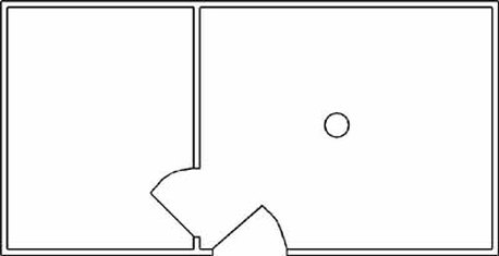
The room on the left is the 8' x 10' control room covered by a permanent roof. Of course the room on the right is the 12' x 10' observing room with a permanent pier placed in the center. The outer door is 32" and the inner door is 30". I've left off the exact dimensions here, but keep in mind that the 20' width and 10' depth are measured from the outer walls. Thus, the actually dimensions of each room is actually a bit less than I have advertised. When designing your own plan, make sure to account for the width of your wall frames, a standard 3.5 inches or the width of your studs.
Knowing that you have a working floor plan, the next step is to figure out how the floor will come together. There are many ways to plan a floor, but whichever method you choose must account for a big hole in it, where your pier will be. Knowing this, I decided to plan my floor using 4x4s riding on cinder blocks and framing the floor joists with 2 x 6s on 16" centers. This is works easily within my planned dimensions.
I laid out my floor like as follows:
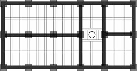
The squares represent the cinder block footings placed 4 feet apart across the width of the structure and 5 feet part from front to back. The thick beams are the 4x4s resting directly on the blocks. The framing is then placed on top of the beams, subsequently nailed into the beams. Total clearance from top of floor to ground is at least 12" depending upon how many blocks I used for each footing. This totally clears my pier foundation, which of course is poured first. Incidently, planning the actual pier footing is rather superfluous. How hard is it to execute a 3' x 3' x 3' block of solid concrete with rebar reinforcements? Just make sure you plan for the floor joists around your pier to clear the pier foundation. These are separate systems and must not touch. You do not want floor vibrations to be translated to the scope!
Therefore, you do not need to prepare a totally level ground for this structure. The amount of cinder blocks you use is dependent upon the level of the ground. Deck blocks aren't quite as flexible here and will require a perfect leveling of the ground in preparation. In lieu of cinder blocks you might decide to use 4x4 piers sunken in concrete. This works equally well since you can simply connect your frame directly to the piers, saving the costs of 4x4 floor beams, and then cutting off the excess 4x4 that rises above the floor after leveling. Then again, you need to ask yourself if you really want to go through the pain of sinking so many piers in concrete? For smaller floor plans this may work well for you since you may need to sink only a little more than your corner piers. But a structure the size of Ballauer Observatory would require at least 12 such sunken piers at a minimum since the floor joists would need quite a few piers to bolt onto. Even if you use 10' stock for your joists, I would not suggest building such a heavy structure on top of a minimum amount of such piers. Bolting your floor joists onto only a few 4x4 piers is not the most stable way to anchor it anyway and will provide too much flexure in the floor. You may have strong pier footings, but your connection to it will be the weak link in the chain. Then again, you can help support such a structure by placing cinder blocks in between the sunken supports. My thinking is that it is still too much work!
That's why I opted for using cinder blocks. Don't worry,the observatory will be plenty heavy enough to stay in place, at least here in Texas where earthquakes aren't much of a threat. High winds don't stand a chance either unless it suffers a direct hit from a tornado. But I figure if that happens I'll be building over from scratch anyway!
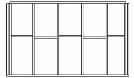
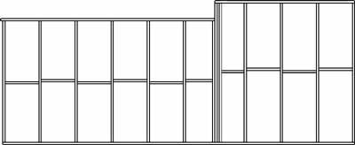
After planning the floor, I had to give consideration to the elevations. Each side of the framing will be a very predictable length and spaced with studs on 24" centers; however, the height of each wall will depend upon your type of roof construction, the height of your telescope pier, or the amount of horizon you want access to while observing.
For me, I didn't care too much about constructing short walls around the observing room since I figured I'd just compensate with a taller pier. But because I decided on a split roof, I knew that I'd need taller walls around the control room so that the rolling roof could easily tuck underneath the section of roof that is fixed. I planned for the walls of the control room to be of standard stud length to allow for a full 8' ceiling, keeping in mind that a single 2x4 plate will ride atop these wall frames. So I just had to decide how tall to make the walls around the observing room. Thus, as shown on the front (North) frame, I calculated a 12" difference (not including the top frame to be added later on only the taller part of the frame) to facilate the necessary space for clearance of the rolling roof:
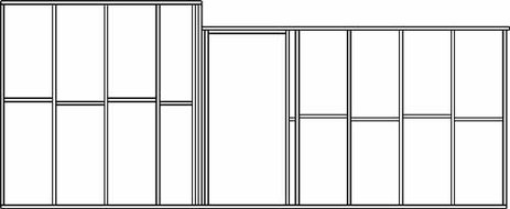
Unfortunately, this meant that the height of the door opening would be an inch shorter than a standard, prefabricated door with frame (a cost I couldn't justify anyway), so I just built my own door from left over siding. Plus, I had to forgo a top plate on this section because that would add an additional 1.5" to the wall height, unless I cheated the door height even more, which I didn't think would look good.
[Update: I wish I'd planned for a standard door in retrospect. Something I could have done by removing that additional brace at the top of the door opening. I just originally feared that the structure needed that extra brace since I was not going to be using a top plate.]
The remaining exterior elevations are quite standard:
|
Looking very closely at the elevations you may have noticed a four things.
1.) Both East/West frames are reinforced with additional corner studs. This is because the length of these walls span exactly 10'. Therefore, the North/South walls span only 19' 5", seven inches short of 20'. Had I not taken 7" away from the North/South elevations (the width of two studs) then those walls would actually be 20' 7" in length. NOT GOOD considering you've already built your floor 20' along that dimension! Thus, the East/West frames extend the full width of the floor and the North/South frames butt into them. 2.) The East frame is taller than the West frame by 12". Remember that the control room does have a higher ceiling and roof than the observing room. 3.) Did you notice that the top 2x4 atop the West frame leaves a stud's width on both ends? That's to accommodate the 4x4 rails that will extend to the west, on which the roof will roll. |
Framing 101...
|
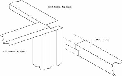
4.) The North/South frames feature a top 2x4 that extends beyond the stud 1.5" (the depth of a standard stud). It would normally have extended 3.5" so that it could be nailed precisely into the top of the West frame (no top plate so you have to nail your frames into something other than through the actual studs). I left some room so that I could notch the 4x4 rails and hammer them into the main structure. Because of height concerns of this section of the roof, I couldn't just run the top rail all the way across; therefore, I had to have a way to mount the rail. By notching the 4x4 it allowed me to hammer into the top of the West frame without raising above the top 2x4 of the North/South frames. So when the angle iron goes in later, it will ride atop the top 2x4s of both the North and South frames and then transition perfectly onto the 4x4 rails that rest on the support poles to the west. See below for illustration:
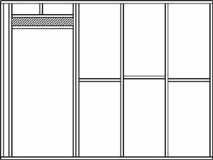
The interior wall must be framed to fit into the existing framing, thus its length is 9' 5". Extra studs are placed where the walls come together to provide nailing space for siding on the west side of the interior wall and sheetrock on the east side.
The height of this interior wall matches the height of the East wall since the permanent roof will rest atop. The framing for the door is standard 6' 10" from floor to jamb. 2x6s are used above the door as "keystone" braces.
I toyed with the idea of building a window into this wall to allow me to see directly from control room to observing room. This was an extra cost I was unwilling to spend but makes a lot of sense. It is important to be able to keep your eye on the scope while in action to guard against the scope choking itself on its cables (it happens). If you plan on using a window then you obviously have to plan your studs around it. It add windows to the North elevation but I didn't have to alter my plans for it since the windows are 20" and fit easily within the studs.
At this point consideration must be given to the roof trusses.
A suggested plan is as follows:
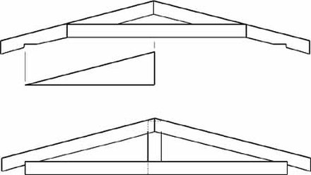
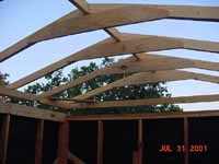
The upper truss as drawn represents the rolling roof portion and the lower is for the permanent roof portion. 7 of the top truss type and 5 of the bottom will need to be built, set in place 24" on center. Building the permanent portion of the roof is pretty easy though I changed the design on the fly. Intending to bracket and toe-nail the top rafters together I discovered that I didn't want to build the trusses on the ground and then raise them into place. 2x6s were used exclusively so each truss can get a bit heavy. Instead, I ran a top 2x6 the entire length of the roof peak and then toenailed the rafters directly into it. This 2x6 extends an additional 12" on both sides to accommodate the eaves. I then notched the rafters to meet the walls and ran ceiling joists the full length of the truss, nailed flush to the rafters. This caused some extra joist to stick up above the top of the rafter but a reciprocating saw or hatchet makes quick work of that. Measuring the notch for the birdmouth is the tough part and took some trial and error. Once I had a standard template cut, I used it to quickly make the other rafters.
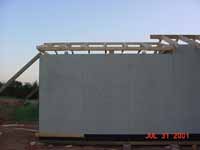
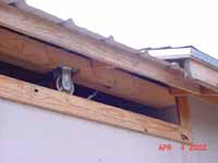
The rolling roof structure came next. Since it's rather difficult to build such a roof atop a ladder, I built the frame on the ground and then lifted it into place. In the above illustration, the upper drawing is the truss for this portion of the roof. I originally planned using 2x6 rafters but later decided on 2x4s to lighten the roof. I also decided to build this part of the roof like the permanent roof in that I used a long 2x6 to nail the rafters into (actually since they don't make a 13' 2x6 - the width of the observation room plus a foot for the western eave- I used two 8' 2x6s pieced together). Likewise, I stacked 2x4s (3 high) together on each side of the truss to make a rail on to which the notched rafters would be attached. The wheels would then attach to these rails as shown below:
The rolling roof structure came next. Since it's rather difficult to build such a roof atop a ladder, I built the frame on the ground and then lifted it into place. In the above illustration, the upper drawing is the truss for this portion of the roof. I originally planned using 2x6 rafters but later decided on 2x4s to lighten the roof. I also decided to build this part of the roof like the permanent roof in that I used a long 2x6 to nail the rafters into (actually since they don't make a 13' 2x6 - the width of the observation room plus a foot for the western eave- I used two 8' 2x6s pieced together). Likewise, I stacked 2x4s (3 high) together on each side of the truss to make a rail on to which the notched rafters would be attached. The wheels would then attach to these rails as shown below:
The drawing shows the rails in a different fashion than I described above. I originally designed it this way because I feared that stacking the three 2x4s on top of each other would add too much height to the rolling roof and thus would not clear the eave of the other roof. After recalculating my measurements I decided I could stack the rails 3 high since I decided to pitch this portion of the roof slighty less (3/12) than that of the permanent roof (4/12). I did this because adding the 2x6 toeboard at the top of the permanent roof actually caused me to worry if the peak of the rolling roof would clear.
Ceiling joists are unnecessary and unwanted in this portion of the roof because you want give more clearance for your telescope and pier. Instead, I used 5' 1x4 braces nailed directly to the rafter to give extra support.
After that, everything else is accomplished on the fly. Additional drawings are not necessary once the main framing is in place. The only other concern is to plan how far away you intend to place your support posts for the roof to roll on to.
Once you have produced a working set of plans for your observatory, construction can begin. In Part Two of this article I will document to construction of Ballauer Observatory with pictures and explanations. You might want to print out the planned drawings I included in this part of the article for use while reading Part Two. Or, you can just reference Part One directly as necessary.
Part 2
Introduction
In the first part of this article I discussed some of the ideas that go into the construction of a roll-off roof observatory and some of the considerations you might overlook in building such a structure. In this half of the article I will show you how I took such principles into account when I built my own observatory. Once again, I hope that you gain a great amount of insight into how you might take the best of what I have already done while leaving all the mistakes to me.
Foundations
You'll have to give consideration, first and foremost, to the foundation(s) of the structure. The critical choice in your decision has to be the method by which you anchor your observing pier to the ground. Secondly, and equally as important, you need to consider how your building structure will relate to that pier.
I expressed my thought on the principles of good pier design in the first article. By now you should know that I believe that the project should use two separate systems, where the observing pier has absolutely no connection to the surrounding structure. Some may argue that putting everything on a single concrete slab would be sufficient and perhaps it might be if visual observing is your only intent. But when doing photography, why take the chance? Two separate systems will allow your scope and cameras to do their work while you are not bound by tippy-toeing around.
Therefore, the Ballauer Observatory utilizes this two foundation system, one of which is the concrete pier support and the other is the wooden pier and beam structure of the building itself.
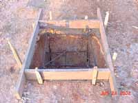
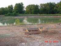
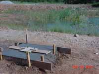
I knew I would use a pier design that would bolt onto concrete slab. In this way, if I ever needed to change or modify the pier then I could simply unbolt it from the slab and place the new or modified pier over the same anchor bolts. Of course this requires planning on how you might setup the anchor bolts in the concrete as it drys. For this purpose a wooden template can be made to hold the anchor bolts in place while you allow the concrete to completely cure.
I.I.D.I.O.T.IIDIOT stands for "If I Did It (an)Other Time" - Look in these boxes for the mistakes I made the first time but would certainly change had I did it again.
|
I.I.D.I.O.T.I used 10" long j-bolts as anchor bolts. Big mistake! I got some movement of the bolts even after the concrete dried. IIDIOT, I would use anchor bolts. You drill the holes for them, hammer them it, and they expand once tightened. They come in a variety of lengths and sizes.
|
As the concrete dries you can begin your work on the floor structure of the observatory. But if you simply have to slap your pier on it for a first test, then I'd suggest allowing the concrete to cure for at least a day before doing so. It takes a while for the concrete to pack around the anchor bolts. Once the concrete has dried, then the forms and template can be safely removed.
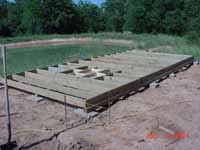
One other point that I may or may not have mentioned in the first article. A good rule of thumb for the size of an all-concrete pier, which once again I opted NOT to do, is 1" diameter per 1" of scope aperture. This makes for a pretty solid pier. When using pipe for your pier, the diameter is not as important as the thickness of the pipe's walls. I used 3/8 inch walled pipe which proved to be very solid indeed. Because of this I could go with a 6" diameter pipe for a 10" scope. Again, the beauty of this pier design is that should I ever upgrade to a much larger scope then I can redesign a new pier to accommodate it. If you have opted for the concrete pier design then I would suggest using a larger diameter than needed in anticipation of future scopes, since your pier would then be truly PERMANENT. After pier construction finished then work begins on the foundation of your observatory floor. Since I used a pier and beam technique, with cinder blocks and 4x4s underneath 2x6 treated floor joists, it was not necessary to assure that the ground surrounding the pier was completely level. In this way I could use any number of cinder blocks necessary at each footing in order to get close to the height I need. This way, only a minimum of digging is required to provide a level beam structure. Because my structure is a rather lengthy 10x20 feet, I used a transom to level my corner supports first. I then found the level of the center supports with a normal carpenter's level. 4x4 piers are then laid on top of the supports according to plan and the floor grid is constructed over the top. |
|
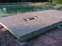
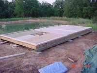
Because the flooring and concrete pier support are two separate systems, care must be made to assured that the floor joists clear the concrete. In this way, any vibrations made to the observatory floor do not translate to the pier itself, and consequently to the eyepiece or camera on your telescope. The floor is reinforced over the pier to provide utility access to the pier itself while giving additional support to this most walked-on area. Treated floor joists are nailed down to the 4x4 beams where possible. This is really the only place where treated wood is required over the entire project, the exception being the 4x4 roof piers that are constructed later. Once the floor grid is complete, I used a layer of OSB followed by another layer of plywood as decking. I simply did not want a whole lot of flexure in my floor. As a result, this floor is indeed pretty solid. The foundation is then finished off by the base plate for the walls, unless you decide to fabricate the entire wall first. For me, I wanted to construct the walls from ground up in the event that my measurements were not precise. Better to replace a board at a time instead of a whole wall in the event of a mis-measurement. |
I.I.D.I.O.T.Since I had a few pieces of particle board laying around I actually used them on the upper deck of the floor. Of course, particle board swells when it gets wet. I knew this, but I was willing to take the chance that I could get the structure waterproof before any rain fell. Of course I was wrong. The result is certainly not a tragedy but water did accumulate on some areas of the particle board. Not too big of deal but it slightly diminishes an otherwise good and solid foundation.
|
Wall Construction
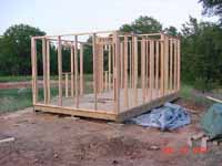
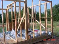
Once the floor is constructed, work can begin on the wall frames. Since I nailed down my base plate first, wall construction would have to be done from bottom to top. This would require toenailing wall studs into the floor plate. This can be avoided if you construct the entire wall individually but I find this method is no easier than the way I did it. And as I said, by working one stud at a time over the afixed plate I can better compensate for mistakes I might have made in pre-planning. In actuality, there really is no right and wrong when doing the framing. The biggest concern is stud placement so as to give yourself something to nail into when you put on your outer siding. Likewise, a properly planned wall frame will give you something to nail into if you decide on using interior siding or sheet rock. Of course that's why we take such care to set our studs on 16" or 24" centers in the first place.
|
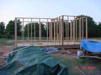
Walls are constructed and tested for squareness as they rise by measuring from corner to corner of each room. Equal measurement suggest that the walls are indeed square. Diagonal braces are notched into the walls to retain squareness and provide rigid support. This is a critical step, in my opinion. A before and after push on the wall frames suggests that without the diagonal braces the walls have entirely too much flexure. Though the exterior siding helps to maintain trueness and to give it strength, reinforcing the wall frames with diagonal braces help to provide additional support and peace of mind.
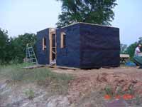
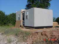
Walls are topped off with a top plate of 2x4s according to plan. Care must be taken to assure than you have provided a way for the external roof rails to be incorporated into the structure. In my case, I had to make sure that the top plates are left a bit short at the west wall, where the roof rails will extend from the structure. Upon completion of framing, preparations can be made for exterior siding. Using tar paper as a vapor barrier is the first step to provide protection from moisture. It's not a critical step unless you are planning to put on interior siding, but its still a good idea if for no other reason that it will make the interiors of your observatory black, something you'll probably want anyway. Because I have windows, this is a good time to frame them into the walls. Likewise, because my control room will have climate control, siding must be placed on the interior wall facing the observing room. This control room will be insulated and entirely enclosed. A window unit air conditioner is also framed into the control room wall, not shown here. These modifications should be made prior to the placement of exterior siding on your structure. In this way the siding can be perfectly cut to size and nailed into place, providing support and squareness all the way to the window frames. Once the siding is in place you will discover that the walls won't budge a whole lot. It really solidifies the structure and the better quality siding you use the more stability you will get. |
I.I.D.I.O.T.I used "project siding" from Home Depot because of its low cost. IIDIOT, I would use the higher quality and stronger A4-type of siding. I have discovered that this project siding has a tendency to warp a bit after a weathering-in period. Though not a serious problem, the better quality siding (could I have afforded it at the time) would have been the better choice.
|
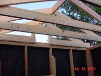
Roof Construction Essentially, I have incorporated two independent roofs structures into my design as you will see. For those of you building single room observatories with a single rolling roof, you should be able to focus only on the rolling roof portion of these construction notes. My concepts on this portion of the roof can be taken pretty directly into your own design, though you may have to device a practical way of enclosing the eaves on the gable ends, when closed, while still allowing a freely rolling roof. That shouldn't pose too big of a problem for you anyway, plus my design can easily be modified in a way specific to your needs. Because of the difference in height of my walls between the control room and the observing room, a consideration which was pre-planned, I knew that I could construct my fixed roof prior to the rolling roof. So that is exactly what I did. The fixed roof portion was constructed with 2x6 rafters and 2x6 ceiling joists, because I planned to put a ceiling in my control room. Both the rafters and ceiling joists were placed on 24" centers. Rafters are nailed at the top into a peak board, another 2x6 in this case, and then notched at the bottom and nailed into the top plate of the walls. This leaves a gap of ~2.5" between roof coverings and top of wall plate, which will be covered by a "bird board" later in construction. |
|
Once the trusses are in place, I needed to trim a bit off the ends of the ceiling joists since they protruded beyond the top of the rafters. This is easily done with either a reciprocating saw or a hatchet.
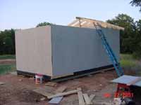
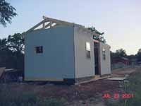
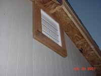
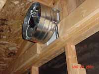
Because I was concerned about heat build-up in the attic area of the control room, I framed an attic fan into the East wall. This fan will serve to direct heat exhaust from the attic to the outside. Since the fan is rated for a greater square footage than this attic area, I put intake holes in the opposite gable, opening into the observing area of the structure. In this way, any hot air that accumulates near the scope will be pulled into the attic of the control room and circulated out through the fan. The fan itself is thermostatically controlled, coming on when attic heat reaches a fixed temperature. The permanent portion of the roof is completed by constructing the eaves, enclosing the gable ends, and applying the plywood (OSB) roof deck. The ventilation slot is made into the opposite gable end of the fan. Roof is then tar papered and covered with composition roofing shingles. I used white shingles to reflect as much sunlight as possible during the day. Remember, this is Texas. It gets awfully hot here in the summer time. Any method that will reduce the amount of heat collected within the observatory will benefit both the safety of the equipment as well as the amount of time required for cooldown at night. Providing good air circulation, bright reflective exterior surfaces and insulation around your control room are excellent ways to battle the summer heat. If cold weather is a concern where you are located then the same principles apply, only you'll want to retain heat instead of exhausting it. Heat absorbing colors and space heaters will work well to retain and circulate warm air through cold environment observatories. Once the main roof is constructed, the rolling roof portion of construction can start. Framing of this 10 x 12 foot roof is accomplished on the ground using 2x4s for trusses placed 24" on center. The same construction techniques are used as on the main, fixed roof. Rafters are nailed into a peak board and notched at the bottom around rails where the 4 inch 'V' grooved coasters are placed. Ceiling joists are not used because scope clearance is a concern. 1x4 braces are nailed into each truss to provide support. |
Once the rolling roof is framed it can be lifted into place atop the observing room. 1x4s are nailed to the interior of the top plate to prevent roof from falling off. The wheels will ride atop angle iron affixed to the top plate. Of course the angle iron cannot be placed until the roof rails and posted are in place, which is the next phase of construction. But first, aluminum roofing material is then put into place, used because of its light weight.
Roll-off Roof Supports
Before the roof can be rolled off the structure, you have to build a rail and column system to hold the roof when the observatory is in use. I sunk four treated 4x4 posts into the ground, two on each side, and set them with concrete. I placed 4x4 rails atop these posts from North to South and set the rails from the observatory atop these. Careful measuring is required to assure that the height of your posts is level with the top plate of your observing room wall. This allows for the roof to roll smoothly from its closed position. I actually made the connections of the 4x4s by drilling holes and bolting them together. At this time the angle iron can be placed atop your rails. Roof should be tested before nailing angle iron in place in order to find the rail position of least resistance. Wooden "stops" are placed at the end on the rails so that the roof can't be accidentally rolled completely off the rails.
At this point, you've actually come to the point where your observatory is complete functionally. Additional touches can be added at money and time allows. But I'd take a little bit of time to set up your scope and see how well you did. Such a "first light" use of your observatory will give you some ideas about what you want to do during the finishing stage.
Finish Work
The amount of work you put in here really depends on your own personal tastes. The door(s) is obviously the next step in order to prevent possible theft of your equipment and tools. Exterior trim can be done during this time. Interior electrical work, insulation, network cabling, and interior siding/trim can be accomplished if necessary. Weatherproofing can be completed. A locking method for the roof can be put in place (I used hooks and turnbuckles). Painting of exteriors and enclosure around the rails can now be done.
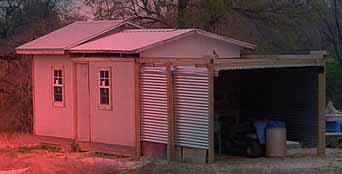
I left the space underneath the roof wheels open. I figured that it would greatly assist in air circulation. Plus, I found that complete enclosure of this area, while maintaining full functionality of the rolling roof, is a tall order. Perhaps some type of rubberized flap can be put into place to keep the insects or birds out of the observing room, but I didn't see that as a critical need. If critters get in I'll just use bug spray. Because the aluminum roof extends out a foot over the rails, rain cannot directly enter the room. Some moisture can still enter but I keep my observing room equipment covered anyway. I can live with a little moisture here as a fair trade for the extra air circulation. Because the footprint of the observatory is increased by the external rail system, I enclosed this area with some corrigated roofing/siding to make a lean-to storage area. It's a good place to keep your lawn equipment and a good use of otherwise useless space. Alternatively, those with kids might be able to mount swings to the underside of the sturdy 4x4 rails. This way you'll have a true multi-function facility.
Conclusion
I've tried to show you the more common areas of observatory construction techniques that are applicable to most all roll-off roof designs. For example, finish work is highly individual in practice, specific to your needs and requirements. Electrical considerations go beyond the scope of this article since I am no Electrician. I would hate to have any of my advice be the cause of a fire at your observatory! I hope you consider these articles a great help to you. For any extra advice please feel free to email me personally at [email protected]. Or just drop me a line to let me know if these articles have been any help to you.
